
Includes everything in include/, and defines main parameters

For my speaker design and my 2u rack design, I adopted the following convention I think it has helped greatly: File/directory It’s all to easy to end up with a monolithic file with a lot of hardcoded variables and confusing modelling. Large projects can be difficult to manage.

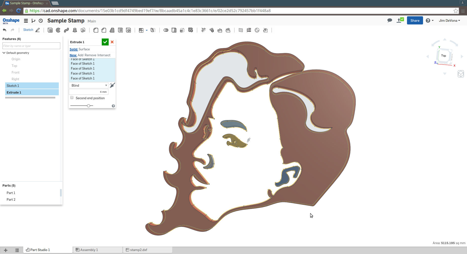
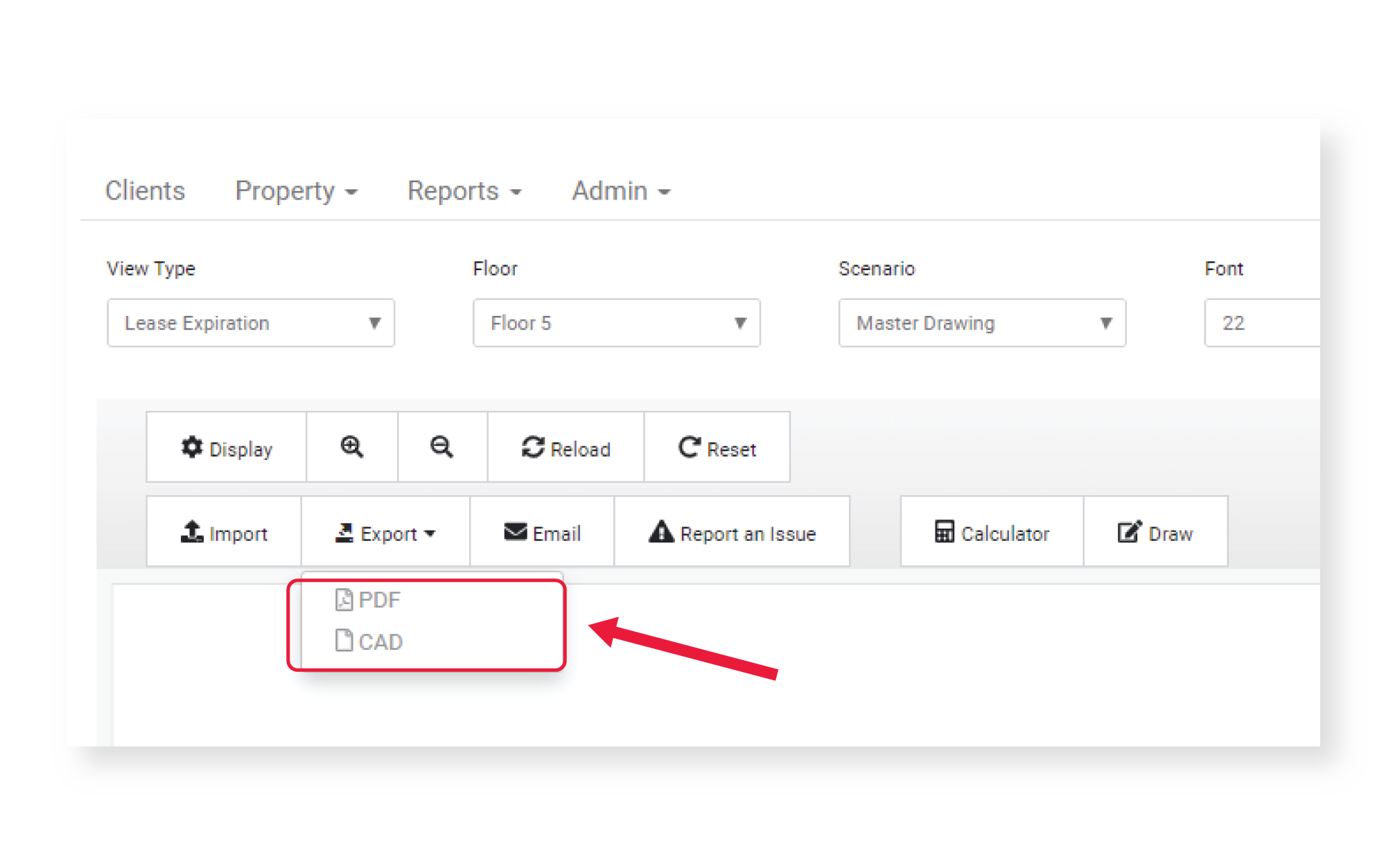
Organise larger projects using directories and files The only caveats are the artefacts in the GL based preview, and the rendering time if you’ve used a lot of curves. As a result, it’s not necessary to do potentially complex trigonometry to position the fixtures. This allows the fixtures to be described negatively and in the same frame of reference as the main subtraction. Difference of a difference, note artefacts Here, for a conduit light adapter design, I used a difference of a difference to effectively subtract a space at an angle, complete with mounting fixtures. Sometimes when describing negative space it’s useful to do a difference of a difference. Module rounded_extruded_square ( l, d ) linear_extrude ( 100 ) offset ( - d ) offset ( d ) cube () Īs stress concentrates at sharp changes in geometry, adding a chamfer or fillet can be the difference between an extremely strong part and one that fails straight away. This is often performed manually using a hull between circles, for example: It’s easy, though, to chamfer/fillet extrusions in negative and positive space. There have been user-land solutions however, but with caveats. OpenSCAD can’t currently chamfer or fillet 3D objects. It’s useful to re-use the 2D objects again for things like holes, supports, etc.The offset transformation allows easy rounding, filleting and shelling if combined with separate 3D operations.No z-fighting, so no marginal adjustments to make sure you avoid co-incident planes.In OpenSCAD, if your design can be described as one or more 2D shapes that can be extruded (etc) into a 3D features, it’s much better to start them in 2D first – here’s why: In this section I’ll detail a few hints I’ve thought about when producing a lot of designs for various things around the house. This allows to produce files that can be used for sheet metal cutting, machining and renders – while allowing for complex designs without creating a mess. I’ve used OpenSCAD 3 to produce a few things that were sent to be manufactured this article shows how I adapt its output capabilities and how I approach a design. 1ĭespite being actively developed, broadly used and powerful 2 there are many shortcomings which make it difficult or sometimes impossible to use outside of 3D printing. It’s popular within the 3D-printing community due to its ability to produce STL files.
#Openscad export svg software#
As it’s script-based, it’s fantastic for parametric design and the files can be version controlled just like a software project. OpenSCAD is an open-source CSG based script-only CAD package.


 0 kommentar(er)
